01 Three impedance levels are not three kinds of lightning - they are three current paths
Your 4 kV surge test report is meaningless without a stated source impedance.
Impedance is the path.
Source impedance is not a setting on the instrument - it is the path the lightning current must travel. Think of it as road width: the wider the road, the more current flows at a given voltage; the narrower the road, the less current flows, but the voltage stress remains.
Remember this pair: a combination wave generator produces a 1.2/50 µs open-circuit voltage wave and an 8/20 µs short-circuit current wave. The same machine outputs voltage when connected open-circuit, and current when connected short-circuit.
The three combination-wave settings are 2 Ω, 12 Ω and 42 Ω. There are also 10/700 µs telecommunication waves with equivalent output impedances of 15 Ω and 40 Ω. Two waveforms, two impedance systems, each corresponding to different ports on the equipment under test (EUT). Section 05 clarifies the boundary; Section 09 maps it to specific models.
02 2 Ω / 12 Ω / 42 Ω: at the same 4 kV, short-circuit current differs by 20×
Put the three settings side by side and the difference is not in voltage - it is in current.
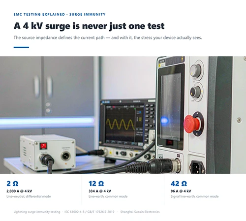
IEC 61000-4-5 provides a table of peak currents. At the same 1 kV open-circuit voltage: 500 A short-circuit current at 2 Ω, 84 A at 12 Ω, and 24 A at 42 Ω. At 4 kV, these become 2,000 A, 334 A and 96 A.
Table 1 - Peak short-circuit current at different source impedances for the same open-circuit voltage (IEC 61000-4-5)
| Open-circuit voltage | 2 Ω (differential mode) | 12 Ω (power-line common mode) | 42 Ω (signal line-to-earth) |
|---|---|---|---|
| 1 kV | 500 A | 84 A | 24 A |
| 4 kV | 2,000 A | 334 A | 96 A |
20×.
From 2 Ω to 42 Ω, the current differs by a full factor of 20. Whether an MOV or a TVS diode can withstand the surge depends on this current - not on the kV shown on the display.
The origin of the three settings is straightforward: 2 Ω is the generator's own impedance; adding a 10 Ω series resistor gives 12 Ω, and adding a 40 Ω series resistor gives 42 Ω. The additional resistor is determined by the test path, not by an options list.
03 2 Ω differential mode: line-to-line on the low-voltage mains, where MOVs are selected
The 2 Ω setting simulates the public low-voltage mains - between line (L) and neutral (N).
This corresponds to differential-mode injection, with no additional resistor on the generator output. The impedance between the mains and the equipment is low and the surge path is short, so the same voltage releases the maximum current.
The MOVs and TVS diodes at the input of electronic equipment are rated by the current of this setting. 4 kV corresponds to 2 kA - the starting point for selecting many power-line protection devices.
If the EUT is a single-phase three-wire, 220 V switching power supply or small home appliance, start with this setting. It is the most severe and the closest to the real path on the mains side.
04 12 Ω common mode: the extra 10 Ω is the path from the equipment to earth
The extra 10 Ω of the 12 Ω setting over the 2 Ω setting represents the grounding loop.
This setting is used for line-to-earth (L/N–PE) testing. The surge current enters through the line and must discharge through the equipment enclosure and protective earth (PE); the path is longer than line-to-line, so the impedance is naturally higher.
The standard sets the line-to-earth voltage level at twice the line-to-line level precisely to account for this difference in path impedance.
A commonly overlooked point: 12 Ω is the 2 Ω generator impedance plus a 10 Ω additional resistor. The additional resistor must be placed in series between the generator and the EUT - put it on the wrong side and the waveform changes.

05 42 Ω vs 40 Ω: do not mix up the two systems
The third combination-wave setting is 42 Ω - 40 Ω of additional resistance plus the generator's 2 Ω - used for common-mode testing of other signal lines to earth. The longer and thinner the line, the higher the source impedance and the lower the current, but the voltage stress is still there.
40 Ω is the equivalent output impedance of the 10/700 µs telecommunication wave generator, formed by two internal matching resistors of 15 Ω and 25 Ω in series. This value is built into the generator, not added externally.
One external, one internal.
One pairs with the 1.2/50 µs combination wave, the other with the 10/700 µs telecommunication wave. The numbers are close, but the paths are different and they cannot be converted into each other. State clearly in the report which setting was used - that is the basis for a sound selection.
06 10/700 µs telecommunication wave: 40 Ω built in, 15 Ω switchable
The 10/700 µs voltage wave is paired with a 5/320 µs short-circuit current wave, designed specifically for induced overvoltages on long-distance communication lines and outdoor signal cables. With a 10 µs front time and a 700 µs time to half value, it lasts far longer than the combination wave.
IEC 61000-4-5 requires its output impedance to be 40 Ω ±10%, formed by internal 15 Ω and 25 Ω matching resistors. Bypass the 25 Ω and only 15 Ω remains, used to accommodate multi-line coupling.
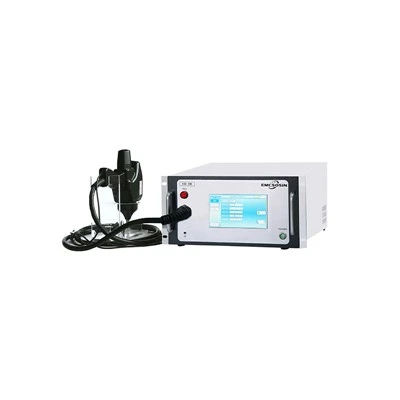
The Suoxin SUR 700L builds both resistance values into the instrument: 0.2–10 kV output, with 5–250 A short-circuit current at 40 Ω.
07 Surge testing does not simulate direct lightning: the scope boundary of the standard
Direct lightning strikes are outside the scope of IEC 61000-4-5. The standard explicitly excludes them.
What it simulates is indirect lightning - the voltages and currents induced on lines when lightning strikes nearby objects or lines - as well as transients from switching operations in the power network and the switching of large inductive loads.
Verifying high-current injection from a direct strike requires a different waveform and a different standard; this generator cannot substitute for it. Describing a combination wave generator as capable of simulating direct lightning is a mistake from the project's outset.
Nor is pass/fail judged by a single "did it break" result. The standard defines four performance criteria - a, b, c and d: normal performance; temporary degradation that self-recovers; temporary degradation requiring manual intervention; and unrecoverable hardware damage.
08 Why tests fail: the coupling network and the 2-meter cable
Most failures are not in the voltage setting - they are in the configuration details.
The power cable between the EUT and the coupling/decoupling network (CDN) should not exceed 2 m. Make the cable longer and added inductance creeps in, distorting the waveform.
The placement of the additional resistor is just as critical. The 2 Ω, 12 Ω and 42 Ω settings depend on the resistor being placed between the generator and the EUT; put it on the wrong side and you will measure a different setting.
The pulse interval should not be too short either. The standard recommends one pulse per minute or slower, giving protection devices time to recover. Forcing a faster rate makes results non-comparable.
09 Select by current path: which segment each of SUR S10 / SUR 700L / SUR T10L covers
Selection is not about who has the higher kV - it is about which path your EUT takes and which impedance the standard requires. All three models cover 0.2–10 kV open-circuit voltage and comply with IEC 61000-4-5 / GB/T 17626.5.
Table 2 - The three models mapped to lightning current paths (parameters from Suoxin's official product pages)
| Model | Waveform | Output impedance | Built-in network | Corresponding path |
|---|---|---|---|---|
| SUR S10 | Combination wave 1.2/50 µs 8/20 µs |
Differential mode 2 Ω Common mode 12 Ω |
Single-phase three-wire AC 220 V / 16 A DC 60 V / 16 A |
Single-phase equipment power port line-to-line 2 Ω line-to-earth 12 Ω |
| SUR 700L | Telecommunication wave 10/700 µs 5/320 µs |
15 Ω / 40 Ω (5–250 A short-circuit current at 40 Ω) |
- | Long-distance communication lines Outdoor signal ports |
| SUR T10L | Combination wave + telecommunication wave | Combination wave 2 Ω (common mode 12 Ω) Telecommunication wave 15 Ω, 40 Ω |
Three-phase five-wire 16 A |
Three-phase equipment - power port + communication port covered in one unit |

The SUR S10 handles combination waves only. 2 Ω differential mode for line-to-line, 12 Ω common mode for line-to-earth - one instrument covers the power ports of switching power supplies, small home appliances and security equipment from R&D pre-compliance through certification.
To obtain the 42 Ω setting, an external 40 Ω additional resistor is added to the 2 Ω combination wave. Use a SUR S10 or SUR T10L to output a 2 Ω combination wave, then insert a 40 Ω additional resistor between the generator and the EUT as the standard requires - that is a signal line-to-earth common-mode test. No dedicated 42 Ω instrument is needed.
The SUR 700L is built for telecommunication waves only, outputting the 10/700 µs voltage wave. 40 Ω is its inherent impedance; bypassing the 25 Ω switches it to 15 Ω for multi-line coupling. It is the instrument for induced-lightning testing of outdoor communication lines and signal ports.
The SUR T10L is a three-phase multi-function instrument: a 1.2/50 µs combination wave at 2 Ω (12 Ω common mode) with a built-in three-phase five-wire 16 A network, plus 10/700 µs telecommunication waves at 15 Ω and 40 Ω. When the EUT requires both power-port and communication-port testing, a single unit replaces two.