Retrofit robotics has been iterating fast in recent years, and application scenarios have grown a lot more complex. EMC (electromagnetic compatibility) standards are being updated and tightened in step, and the bar keeps rising for both immunity and emission performance.

Image sourced from the internet
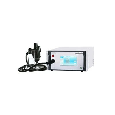
In the development and certification of robots, industrial control equipment, and new-energy products, electrostatic discharge and impulse magnetic fields are the two most common interference risks. ESD is the most frequent offender - it can freeze equipment, scramble programs, or damage ports outright. ESD immunity testing relies on an ESD gun, which reproduces human-body static, contact discharge, and air discharge in line with the latest edition of IEC 61000-4-2, verifying how well a product tolerates static events.

Impulse magnetic field interference tends to show up in industrial sites with high-power motors, contactors, and transformers. Strong magnetic fields disturb internal sensors and signal circuits, and data errors follow. An impulse magnetic field simulator reproduces the field strengths specified in IEC 61000-4-9, checking that the product keeps working reliably in that environment.

EMC compliance today is a prerequisite for stable deployment and volume shipping - simply "passing the test" is no longer enough. Standards are changing, so are applications, and R&D and test teams need to refresh their test plans accordingly: pick instruments that match the new editions, screen out compatibility risks early, and the product will run reliably in harsh industrial environments while clearing both domestic and international certifications.
Here is my summary of the new EMC test requirements for industrial robots.
1. Where EMC requirements are heading
EMC capability is climbing a ladder: traditional EMC → system-level EMC → network-cooperative EMC → safety-controller integration. The new edition adds four core orientations:
1. Wider port coverage than before;
2. Higher immunity class requirements;
3. Communication performance now counts as an evaluation metric;
4. Functional states must be verified in sync and tied into functional safety.
Assessment spans four dimensions - electromagnetic emission, immunity, cybersecurity, and environmental adaptability - and produces five deliverables: emission limits, immunity class, port configuration, functional verification, and documentation plus risk assessment.
2. Ports, cables, and grounding are the foundation
How well a robot system handles EMC comes down to port configuration, cable selection, and grounding structure:
· Ports involved: power, I/O, communication, and encoder interfaces;
· Control measures: cable routing, shield handling, protective earthing, filter design;
· Field risk: cable crossovers are prone to electromagnetic crosstalk. Routing, grounding, and shielding should be designed together at the integration stage.
3. System-level EMC test setup
Testing no longer looks at the controller, servo, or robot body in isolation. Instead, a complete robot workstation is set up - robot body, control cabinet, servo drives, teach pendant, industrial network devices, signal generation, and coupling/decoupling units all in place - and four categories are assessed together: emission, immunity, port performance, and functional margin.
4. The two core test items
4.1 Emission testing (radiated + conducted)
This measures the electromagnetic energy a robot releases during normal operation. It splits into radiated and conducted emission tests; results are checked against limit lines, and risky spectral peaks get flagged.
4.2 Immunity testing (disturbance injection + functional verification)
Disturbance signals are injected into the power port, communication ports, I/O ports, and protective earth while the robot's status is monitored continuously:
· running mode, position control, emergency stop, communication response, alarms, and deviation monitoring;
The point is simple: confirm that the robot keeps functioning and stays safe under interference.
5. New EMC risks from industrial communication networks
Robot controllers, servo drives, sensors, teach pendants, and edge gateways are networked through industrial buses, communication cables, and wireless interfaces. When electromagnetic interference hits, the network feels it first: signal-to-noise ratio drops and jitter grows, then bit errors, latency swings, and abnormal control commands follow - and in the worst case, the whole machine goes down. That is why network-cooperative scenarios are a focal point of the new EMC edition.
6. Joint verification of functional safety and EMC
EMI noise can couple into safety circuits, so EMC and functional safety have to be verified together:
· Covering safety functions such as emergency stop, safety limits, speed limiting, actuators, safety sensors, torque monitoring, and communication;
· Acceptance criteria: state retention under disturbance, correct safety responses, effective fault diagnosis, and contained risk of unintended activation.
Interference shifts signals, so the system has to judge through its safety mechanisms - that is how functional margin gets verified.
7. Compliance evaluation and the design loop
EMC is not a one-off test. It is a closed loop:
system partitioning → risk assessment → EMC design → test & verification → compliance evaluation → simulation analysis
Evidence package: interface matrix, test plan, equipment parameters, layout drawings, grounding documentation.
When tests reveal deviations, log the issues, feed them back into the design, retest, and keep iterating until the results hold.