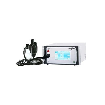
IEC 61000-4-29:2026 (Edition 2) is a technical revision. At its core, it moves DC-port voltage dip and interruption testing from the old general framework toward a quantified verification system matched to 380 Vdc–800 Vdc and higher DC architectures: the test generator must cover 120% of the highest rated voltage, deliver steady-state current up to 120% of the EUT rating, and provide 100 A peak inrush capability at the 650 V class. Short interruptions distinguish, for the first time, between high- and low-impedance modes; voltage step edges are limited to 0.5–50 µs and must be verified with a 100 Ω purely resistive load. Its technical focus is not "stricter limits" but better reproducibility and closer alignment with real operating conditions.

Table 1 - Key changes in IEC 61000-4-29:2026 (Edition 2)
| Criterion | 2026 requirement | Clause |
|---|---|---|
| Steady-state current margin | Generator output ≥ 120% of EUT rated input current | §6.2.1 |
| Peak inrush drive | 24 V/50 A, 48 V/100 A, 110 V/220 A, 650 V/100 A | §6.2.2 |
| Dual-mode short interruption | Low-impedance absorbs reverse current / high-impedance ≥100 kΩ | §6.2 |
| Voltage step edge | 0.5–50 µs (100 Ω load), overshoot/undershoot <10% | §6.2.1 |
01 The standard targets the DC input port
First, a common misconception needs correcting: IEC 61000-4-29:2026 is not a product standard tailored to any one category of equipment. The standard is explicit - it does not specify which tests a particular device or system must undergo; instead, it gives product committees a general method. Which levels to select and how to set performance criteria are decided by the product standard.
Energy storage converters, PV inverters, and EMS power supply controllers are simply typical equipment with DC-side ports. As long as the EUT draws power from a DC bus, the three disturbance types - dips, interruptions, and voltage variations - are in scope.
Ripple is outside the scope of this standard.
02 Twenty-six years between editions - only three changes really landed
This July 2026 edition overturns the 2000 configuration of 360 V and 25 A. Three areas were revised: output voltage, low-impedance interruption current limiting, and the verification load.
The upper output voltage limit is now 120% of the highest rated UT. Typical UT values listed are 24, 48, 110, 300, and 650 V, with a 780 V source recommended for general laboratories.
Low-impedance short interruptions gained a current-limiting condition: for EUTs rated above 110 V, the generator may limit current to within ±200% of rated input current.
The load used to verify switching characteristics and peak inrush drive capability was also clarified. If the report uses the wrong load, the data are not comparable.
03 The 120% steady-state current is the generator's output capability, not the EUT's nameplate
The 120% refers to the generator, not the EUT under test. This is the most-quoted figure and the one most often reversed.
The standard requires the generator's rated output current to cover at least 120% of the EUT's rated input current. During a disturbance, port voltage sags and the EUT draws more current to maintain power.
If the source has no headroom and hits current limit, the so-called 40% UT dip is no longer the waveform the standard defines. Strictly speaking, that is not a test at the dip level at all - what you measured is the source's limit.
25 A remains the general recommendation, but it is a starting point covering most scenarios, not a ceiling. EUTs at the 650 V class often draw far more than that.
04 Peak inrush: 100 A at 650 V, but 220 A at 110 V
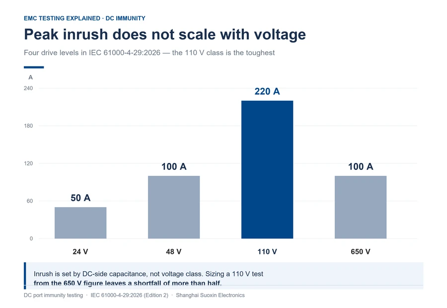
The 650 V class requires only 100 A, while the 110 V class requires 220 A - this table does not scale linearly with voltage. The four classes are: 24 V → 50 A, 48 V → 100 A, 110 V → 220 A, and 650 V → 100 A.
Do not infer current from voltage by intuition.
Inrush current is set by the charging current of the EUT's DC-side capacitors. Low-voltage, high-current systems use larger capacitor banks and see higher surges - the trend runs counter to voltage class.
The requirement also covers both directions: the generator must source peak current into the EUT and absorb current fed back from it. A supply that only sources in the forward direction is non-compliant.
Sizing a 110 V test using the 650 V figure leaves a shortfall of more than half.
05 Dual-mode short interruption adds current limiting under low impedance
The 2000 edition already defined two impedance conditions for short interruptions. In low-impedance mode the generator output impedance is <0.5 Ω; in high-impedance mode it is >100 kΩ.
High-impedance interruption simulates a physical disconnect on the supply side (e.g., a circuit breaker opening or a contact separating). The port presents a high-impedance state, testing the equipment's internal energy storage, control logic, and state retention when it is completely cut off from its energy source.
Low-impedance interruption simulates the DC bus being short-circuited or clamped through a low-resistance path (e.g., a protective short circuit, or the bus capacitor being rapidly discharged by an external circuit).
Edition 2 adds a current-limiting clause on this basis: under low-impedance conditions, for EUTs rated above 110 V, the generator may limit current to within ±200% of the EUT's rated input current during a low-impedance short interruption.

06 Edge time of 0.5–50 µs: a quote stating 1 µs is likely using the old edition
The 2000 edition started at 1 µs; this edition tightens the lower bound to 0.5 µs while keeping the upper bound at 50 µs.
Read the measurement conditions together: with a 100 Ω resistive load on the generator, rise and fall times must fall between 0.5 µs and 50 µs, with overshoot and undershoot below 10% of the voltage change.
This clause rules out most bench power supplies. Their slew rates are measured in V/ms, so they cannot produce microsecond-scale steps; measured against a 100 Ω load, the edge stretches into a ramp.
Verification must be done at the highest UT covered. An edge measured at 48 V in one lab cannot vouch for the 650 V class.

07 What to check after the disturbance: a clean restart, and whether communication came back
Voltage recovery is not the same as passing. The criteria look at how the EUT behaves during the disturbance window. Between normal operation and unrecoverable loss of function or data, there are intermediate levels that require manual intervention to recover. The product standard picks one of these as the acceptance line.
For energy storage and PV equipment, two observation points matter more than whether the device powers back on.
One is the restart after the disturbance. Whether it locked up, whether a manual reset was needed, and whether protection relays operated spuriously all need to be recorded in the report.
The other is communication and status reporting. Whether CAN or Modbus dropped out during the interruption window, whether the backend received a burst of false alarms, and whether data resumed cleanly after recovery.
After restarting, retest using the cold-start and restart procedures in Annex B.
08 Six questions on DC-port immunity
Q1 | Was high-impedance interruption added in the 2026 edition?
No. The 2000 first edition already distinguished high- and low-impedance. What is new here is the current-limiting clause for low-impedance interruption and the explicit 100 kΩ criterion on the high-impedance side.
Q2 | Is the 120% steady-state current a requirement on the EUT?
No. It applies to the generator: its rated output current must cover at least 120% of the EUT's rated input current.
Q3 | If the 650 V class is 100 A, is the 110 V class higher?
Yes. The 110 V class requires 220 A, the highest of the four. Inrush current tracks the DC-side capacitance, not voltage class linearly.
Q4 | Can a programmable DC power supply serve as the generator?
Annex A accepts this architecture, but it must meet the 0.5–50 µs edge, bidirectional peak inrush, and switching between both impedance modes at the same time. Most bench supplies fail on the edge time and reverse-current absorption.
Q5 | Can old reports still be used?
It depends on which edition they cite. A report without a version number cannot be judged; data across editions or verification loads cannot be borrowed from one another. Reissue the report to whichever edition the product standard specifies.
Q6 | Does ripple testing count as a DC-port dip?
No. Ripple belongs to IEC 61000-4-17; dips, short interruptions, and voltage variations belong to this standard. The two reports cannot substitute for each other.