ESD (electrostatic discharge) in EMC (Electromagnetic Compatibility) is a common interference issue in electronic devices, which can lead to device restarts, data loss, or hardware damage. The following is a general ESD rectification plan, covering equipment, testing, and rectification steps.
1. Common Causes of ESD Issues

- Insufficient shell design: too many gaps and holes, resulting in static electricity directly into the internal circuit.
- Insufficient interface protection: TVS diodes, filtering capacitors, and other protective devices have not been added at the interface.
- Improper material selection: the shell material has poor electrical conductivity and cannot effectively shield static electricity.
- Poor grounding: The grounding impedance is too high or the grounding path is incomplete, and static electricity cannot be discharged effectively.
- PCB design defects: signal lines and power lines are not protected, and sensitive components are not shielded.
2. ESD Rectification Plan
Structural design rectification
- Reduce gaps: Optimize the housing design to reduce gaps and holes, and seal with conductive foam or adhesive strips if necessary.
- Add shielding: Add metal shielding covers to sensitive areas to ensure a good connection between the shielding covers and the ground.
- Material selection: Use materials with good conductivity or add a metal coating inside the plastic casing.
Grounding design rectification
- Single point grounding: Ensure that all grounding paths are concentrated to a single point to avoid grounding loops.
- Low impedance grounding: Use a wide and short grounding wire to reduce the grounding impedance.
- Grounding continuity: Ensure that the grounding parts such as the housing, PCB, shielding covers are properly connected.
PCB design rectification
- Add protective devices:
Add TVS diodes, varistors, RC filtering circuits, etc. to the signal and power lines.
Add ESD protection devices (such as TVS arrays) at the interface.
- Optimize wiring:
Keep sensitive signal cables away from the board edges and interfaces.
Avoid long-distance parallel wiring to reduce coupling interference.
- Add filtering capacitor:
Add decoupling capacitors (such as 0.1 μF and 10 μF capacitors) at the power input and sensitive device accessories.
Interface protection rectification
- Add TVS diodes: Add TVS diodes at interfaces such as USB, HDMI, RJ45, etc. to absorb electrostatic energy.
- Use common mode inductors: Add common mode inductors on the differential signal lines to suppress common mode interference.
- Add filtering capacitor: Add a filtering capacitor (such as 100pF) on the interface signal line to filter out high-frequency interference.
Software anti-interference design
- Add watchdog: Prevent the device program from running due to ESD interference
- Data verification: Perform CRC verification or redundancy design on critical data to prevent data loss.
- Delay reset: When an abnormality is detected, delay reset is used to avoid accidental triggering.
3. ESD Testing and Verification
1) Test Standard

Please conduct ESD tests
contact discharge (2kV/4kV/6kV/8kV)
air discharge (2kV/4kV/8kV/15kV)
in accordance with IEC 61000-4-2 and GB/T 17626.2 standards.
2) Testing Instruments
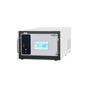
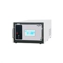
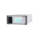
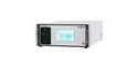
Using our self-developed ESD 20K, electrostatic discharge generator, which has the following features:
① High-precision output: support contact discharge and air discharge, voltage range 0.2kV ~ 20kV, resolution 0.1kV.
② Intelligent operation: equipped with a touch screen interface, supporting automatic and manual testing modes.
③ Compliant with standards: IEC/EN 61000-4-2, GB/T 17626.2 and other standards.
④ Multi-functional application: suitable for ESD testing in electronic equipment, automotive electronics, medical equipment and other fields.
3) Test Point Selection
Test the parts of the device that are easily affected by ESD (susceptible to ESD), such as the shell, interfaces, keys/buttons, and gaps.
4) Test Result Analysis
Record the performance of the device during testing (such as restarts, crashes, data anomalies, etc.) and locate the problem points.
4. Common ESD rectification Tools and Components
1) TVS diode: used to absorb transient high voltage, protect interfaces and circuits.
2) Varistor (MOV): used for ESD protection of power ports.
3) RC filtering circuit: used to filter out high-frequency interference.
4) Conductive foam/conductive adhesive strip: used to seal the gaps of the shell and enhance the shielding effect.
5. ESD Rectification Process
1) Problem positioning: Determine the inlet and influence range of ESD interference by testing.
Use EMCSOSIN ESD generator for accurate testing and quick identification of problem point.
2) Scheme design: Develop a rectification plan based on the problem points (such as adding protective devices, optimizing grounding, etc.)
3) Implement rectification: Modify the design or hardware according to the scheme
4) Verification test
① Perform ESD testing again using our company ESD simulator to ensure the effectiveness of the rectification.
② EMCSOSIN ESD simulator supports a variety of test modes to simulate the electrostatic discharge scenario in real environment, ensuring the comprehensiveness of the test.
5) Optimization iteration: Further optimize the design based on test results
6. ESD Rectification Precautions
1) Advance Planning: Consider ESD protection during the early stages of product design to avoid high costs for later rectification.
2) Comprehensive Protection: Combining hardware, software, and structural design to improve the anti-ESD ability all around.
3) Test Coverage: Ensure that tests cover all possible ESD interference scenarios.
EMCSOSIN ESD generators support various voltage levels and testing modes, which can meet the testing requirements of different scenarios.
4) Try to choose cost-effective solutions on the premise of meeting ESD protection requirements.
7. ESD Simulator Recommendation
During the ESD rectification process, our company's electrostatic discharge generator is an essential testing tool. The following are our recommended products:
1) ESD 20K, ESD 30K ESD generator

Features
- Voltage range 0.2~20kV, 30kV, resolution 0.1kV
- Intelligent operation with 7-inch touch screen interface.
- Comply with IEC 61000-4-2, GB/T 17626.2 and other latest standards
- PC control operation and printable test report
- Support contact discharge and air discharge
- Built-in international standard test level parameters, easy to operate
- Programmable operation, easy to complete the test with one click
- Support one click switching between Chinese and English language
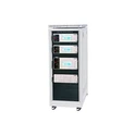
2) RV ESD

Features
- Voltage range 0.2~30kV, resolution 0.1kV
- Intelligent operation with 7-inch touch screen interface.
- Comply with IEC 61000-4-2, GB/T 17626.2, ISO 10605 and other latest standards
- Different discharge RC networks, complying with automotive ISO 10605 standard
- PC control operation and printable test report
- Support contact discharge and air discharge
- Built-in international standard test level parameters, easy to operate
- Programmable operation, easy to complete the test with one click
- Support one click switching between Chinese and English language
The ESD generator can effectively improve the antistatic ability of the product and ensure that it meets the relevant electromagnetic compatibility standards. For more detailed info, please feel free to contact us. Thank you!