1. What is lightning surge immunity test?
The purpose of lightning surge immunity test is to establish a common benchmark for evaluating the performance of electrical and electronic equipment when subjected to surges (impacts). The international standard for surge immunity test is IEC/EN 61000-4-5: Electromagnetic Compatibility (EMC) testing and measurement techniques - surge immunity test. The standard describes two different waveform generators, one is combination wave generator (1.2/50μs voltage waveform, 8/20μs current waveform), which is for power line port testing. Another type is a combination wave generator that meets the requirements of the International Telecommunication Union Commission (10/700μs voltage waveform, 5/320μs current waveform), which is for signal/communication line ports testing.
To simulate the surge pulses caused by lightning strikes or switching transients originated from switching disturbances and systems faults and to evaluate the performance of device subjected to lightning surges, IEC/EN 61000-4-5 standard requires that the tested equipment (EUT) must generate combination waveform (1.2/50μs open-circuit voltage waveform, 8/20μs short-circuit current waveform) under the specified live (DC or AC power supply) working state.
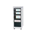
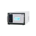
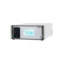
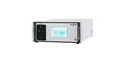
EMCSOSIN SUR series surge generator can generate these waveforms.
2. What is coupling/decoupling network (CDN) in lightning surge immunity test?
The function of the coupling network is to transmit the surge signal of the combination wave generator (lightning surge generator) to the EUT, limiting the current flowing from the power line into the combination wave generator to cause damage to the generator, and reduce the impact on the surge waveform. The function of the decoupling network is to provide sufficient decoupling impedance for the surge wave to prevent the surge from entering the grid and adversely affecting the non-tested equipment powered by the same power source. In addition, other devices connected to the same power supply may contain lightning protection devices. Without the use of decoupling network, lightning protection devices on non-test equipment may prevent the application of surges on the EUT and affect the results of surge test.
EMCSOSIN surge generator contains internal/external single phase or three phase coupling decoupling network (CDN), with customized current as per customer testing requirements.
3. Coupling/decoupling network (CDN) designing structure and circuit parameters
1) Coupling network
The general coupling methods for surge signals to EUT include capacitive coupling and gas discharge tube coupling. The latter has obvious influence on the output waveform of the combination wave generator, so the former is more common. If a small coupling capacitance value is selected, the residual surge voltage on the power supply side is lower, but the efficiency of generating surge current is lower. If a large coupling capacitance value is selected, the coupling efficiency to EUT is higher, but the residual voltage is higher. To balance output efficiency and residual voltage issues, the national standard specifies that line-to-line coupling (differential mode) adopts 18μF capacitance, line-to-ground coupling (common mode) using 9μF capacitance. The source impedance of the low-voltage power grid to the ground is 12Ω. For a combination wave generator with a virtual impedance (defined as the ratio of the peak open circuit voltage to the peak short circuit current) of 2 Ω, an additional 10Ω resistor needs to be connected in series during line-to-ground coupling to increase the effective source impedance.
2) Decoupling network
The decoupling network generally consists of LC low-pass filters which is composed of decoupling inductor "L" and decoupling capacitor "C". The equivalent circuit diagrams of the line-to-ground and line-to-line decoupling networks, where Rs and R′s are the source impedances of the surge power supply. Rs=12 Ω in the line-to-ground case, and the voltage transfer functions of the R′ circuit in the line-to-line case is s=2 Ω respectively.
4. The characteristics of the CDN
IEC/EN 61000-4-5 standard specifies the characteristics of the CDN, which shall be measured under open-circuit conditions (load greater than or equal to 10 kΩ) and under short-circuit conditions (less than 0,1 Ω) at the same set voltage.
The residual surge voltage measured between surged lines and ground on the a.c./d.c. power port of the decoupling network with EUT and mains supply not connected shall not exceed 15 % of the maximum applied test voltage or twice the rated peak voltage of the CDN, whichever is higher.
The unwanted surge voltage measured between non-surged lines and ground with EUT and mains supply not connected shall not exceed 15 % of the maximum applied test voltage (open-circuit).

For more info of EMCSOSIN surge generator, please do not hesitate to contact us at any time. Thank you!