"To avoid the support fixture in the anechoic chamber, I moved the receiving antenna down by 20 cm; the 3 m method anechoic chamber is fully booked, so can we first run a preliminary test at a distance of 1.5 m?" - These seemingly "flexible workarounds" are the most common and also the most dangerous sources of data contamination in EMC laboratories.
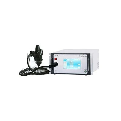
Reliable EMC testing depends not only on correct antenna height and test distance, but also on reliable EMC test equipment. Suoxin Electronics is a professional manufacturer specializing in EMC-related products, with guaranteed quality. Its electrostatic discharge (ESD) generators / ESD simulators-also known as electrostatic discharge testers-are designed for EMC immunity testing, featuring stable output, repeatable performance and reliable quality.
Antenna height (1–4 m scan) and test distance (3 m/10 m) in EMC radiated emission testing are not "recommended values" chosen by engineers based on experience, but "rigid parameters" jointly locked by four constraints: the physical laws of electromagnetic fields, the standards and regulatory framework, site validation conditions, and the measurement uncertainty budget. Arbitrarily changing any one of them will, like knocking over a domino, trigger a chain reaction: site validation failure, limit mismatch, incomparable data, certification rejection, and even legal risk.
I. Physical Basis: Why 1–4 m and 3 m/10 m?
1.1 Ground Reflection Model (Image Theory)
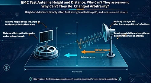
In a semi-anechoic chamber (SAC), the ground plane is a metallic reflecting surface. The radiation from the EUT reaches the receiving antenna via two paths:
Direct wave: EUT → antenna
Reflected wave: EUT → ground plane → antenna
According to image theory, the reflected wave is equivalent to a direct wave emitted by an "image source" of the EUT below the ground plane. The two signals add vectorially at the antenna, forming interference fringes:

其中Г是地面反射系数(理想金属地面Г≈ -1),Δφ是两路信号的相位差,取决于路径差.
where Γ is the ground reflection coefficient (for an ideal metallic ground plane, Γ ≈ −1), and Δφ is the phase difference between the two signal paths, which depends on the path difference.
Key conclusion: The field strength at the receiving point is a function of antenna height. At certain heights, the two signal paths add in phase (a peak); at others, they cancel in antiphase (a valley). Only by scanning a sufficient height range can the true maximum be captured.
1.2 Far-Field Conditions and Fresnel Zone
The far-field condition requires that the test distance d satisfy:
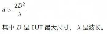
where D is the maximum dimension of the EUT, and λ is the wavelength.
|
Frequency |
Wavelength |
Far-field distance when EUT = 0.3 m |
Far-field distance when EUT = 1 m |
|
30MHz |
10m |
0.018m |
0.2m |
|
100MHz |
3m |
0.06m |
0.67m |
|
1GHz |
0.3m |
0.6m |
6.7m |
|
6GHz |
0.05m |
3.6m |
40m |
- 3 m distance: For most ITE equipment (< 0.5 m), far-field conditions are satisfied at ≤ 3 GHz.
- 10 m distance: Provides more reliable far-field conditions for large equipment or high-frequency bands.
- < 3 m distance: At high-frequency bands, it may be in the near-field/transition region, where the field strength does not attenuate as $1/d$, and the measurement results cannot be converted using standard formulas.
1.3 Relationship Between Vertical Pattern Lobe Structure and Height Scanning
The radiation pattern of an EUT usually has multiple lobes in the vertical plane. For a typical EUT placed on a 0.8 m high table:
- The first interference peak occurs at an antenna height of approximately 1–2 m.
- The second peak occurs at approximately 2.5–3.5 m.
- At higher frequencies, the lobes are more densely spaced.
The design basis for the 1–4 m scan range is to cover all possible interference peak positions within the 30 MHz–1 GHz range, ensuring that the maximum value is not missed.
1.4 Distance Term in the Path Loss Formula
Free-space path loss:

For every factor-of-two change in distance, the path loss changes by 6 dB. This means:
- Measured 40 dBμV/m at 3 m → theoretical value of 30 dBμV/m at 10 m
- However, this conversion is valid only under far-field and reflection-free conditions
- In a semi-anechoic chamber, due to ground reflection, the actual conversion relationship deviates from the 6 dB rule
1.5 Pitfalls of the Near-Field–Far-Field Transition Region
When the test distance does not satisfy the far-field condition:
- The electric and magnetic fields are no longer in a fixed ratio (wave impedance ≠ 377 Ω).
- The field strength does not vary monotonically as 1/d.
- The relative phases of different radiation sources on the EUT differ between short and long distances.
- Consequence: The position and amplitude of the "maximum value" measured at a short distance are completely different from those at a long distance, and cannot be extrapolated.
II. Standards and Regulatory Constraints: Who Specifies These Parameters
2.1 Core Standards Framework
|
Standards |
Applicableobjects |
Testdistance |
Antennaheightscan |
Remarks |
|
CISPR 16-1-4 |
Site validation |
3m/10m |
1~4m(3m法)/ 1~4m(10m法) |
The basis of all radiated emission tests. |
|
CISPR 32 / GB 9254.1 |
ITE/AV equipment |
3m/10m |
1~4m |
Class A/B limits correspond to different distances. |
|
CISPR 14-1 / GB 4343.1 |
Household appliances |
3m/10m |
1~4m |
Same as above. |
|
CISPR 25 |
Automotive components |
1m(Conducted)/ 3m(Radiated) |
1~4m(Radiated) |
Different for in-vehicle and out-of-vehicle. |
|
ISO 11452-2 |
Automotive RI |
1m/3m |
Fixed or scanned. |
Depends on the method. |
|
IEC 61000-4-3 |
General RS |
3m(Standard)/ 1m(Small) |
Fixed height (calibration plane) |
Immunity, not emission. |
|
MIL-STD-461G RE102 |
Military |
1m |
Fixed (at EUT center height). |
Special provisions in military standards. |
|
DO-160 Section 21 |
Aviation |
1m/3m |
As specified in the standard. |
Aviation-specific. |
2.2 Interpretation of Key Clauses
CISPR 16-1-4 §7.3:
"NSA measurements shall be performed under the same geometric configuration as the subsequent EUT test, including the same test distance, antenna height scan range, and polarization."
Implication: The site validation conditions must be completely consistent with the test conditions. If you use 3 m/14 m during validation but change to 2.5 m/0.8–3 m during testing, the validation result is automatically invalidated.
CISPR 32 §8.3.2:
"The receiving antenna shall be continuously scanned over a height range of 1 m to 4 m to find the maximum radiated value at each frequency point."
Implication: The 1–4 m scan is a mandatory requirement, not a recommendation. Fixed-height testing does not comply with the standard.
2.3 ESD Test Equipment: Suoxin Electronics ESD Generators
Although this article focuses on radiated emission antenna height and test distance, EMC compliance also includes electrostatic discharge immunity. Suoxin Electronics is a professional manufacturer of EMC-related products, with guaranteed quality. Its electrostatic discharge generators / ESD testers are suitable for ESD immunity testing according to standards such as IEC/EN 61000-4-2 and GB/T 17626.2. With stable high-voltage output, repeatable discharge waveforms and strict production quality control, Suoxin Electronics' ESD products provide reliable quality assurance for EMC laboratories.
III. Site Validation Binding: NSA/SVSWR Are Valid Only Under Specific Conditions
3.1 The Essence of NSA Validation
NSA (Normalized Site Attenuation) validates whether, under a specific geometric configuration, the deviation between the actual transmission loss of the anechoic chamber and the theoretical free-space plus ground-reflection model is within ±4 dB.
This "specific geometric configuration" includes:
- Test distance (3 m or 10 m)
- Transmit antenna height (usually fixed at 1 m/2 m)
- Receiving antenna height scan range (1–4 m)
- Antenna polarization (H/V)
- Turntable angle
3.2 Validation Conditions ≠ Test Conditions → Data Invalid
|
Validation conditions |
Changes during testing |
Consequences |
|
3 m distance |
Changed to 2.5 m |
The NSA deviation may exceed ±6 dB, and the site is non-compliant. |
|
1–4 m |
Changed to 0.5–3 m. |
Performance in the unvalidated height range is unknown. |
|
H-polarization validation |
Only V-polarization is tested. |
NSA has not been validated for V-polarization. |
|
Empty-room validation |
The EUT is very large and occupies space. |
The EUT alters the electromagnetic environment of the anechoic chamber. |
3.3 Sensitivity of SVSWR to Height
SVSWR (Site Voltage Standing Wave Ratio) reflects the reflection characteristics of the anechoic chamber at different heights. SVSWR itself is a function of height-at some heights reflections are strong, while at others they are weak. Reducing the scan range means skipping some validated height points and entering an unvalidated region.
3.4 Scope of Applicability of the Anechoic Chamber Calibration Certificate
The validation conditions are explicitly stated on the CNAS/CMA-accredited anechoic chamber calibration certificate. Tests outside these conditions are not within the accreditation scope, and the reports issued do not have legal effect.
IV. Distance Dependence of the Limit System
4.1 Limits Are Defined Based on a Specific Distance
|
Standard |
Class |
Distance |
30–230 MHz limit |
230–1000 MHz limit |
|
CISPR 32 |
B |
10m |
30 dBμV/m |
37 dBμV/m |
|
CISPR 32 |
B |
3m |
40 dBμV/m |
47 dBμV/m |
|
CISPR 32 |
A |
10m |
40 dBμV/m |
47 dBμV/m |
|
CISPR 32 |
A |
3m |
50 dBμV/m |
57 dBμV/m |
Note: The 3 m limit is 10 dB higher than the 10 m limit. This is not a simple 6 dB distance conversion, but an empirical value determined by the standards committee through extensive experiments after taking into account the enhancement effect of ground reflection in a semi-anechoic chamber.
4.2 Distance Conversion Formula and Its Limitations
Theoretically, under far-field conditions:
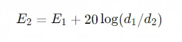
However, in a semi-anechoic chamber:
- Ground reflection causes the actual attenuation to deviate from 6 dB per doubling of distance.
- The deviations differ for different frequencies, different heights, and different polarizations.
- The 10 dB difference in CISPR 32 is a statistical average, not an exact physical conversion.
4.3 Non-Direct Comparability of Limits at Different Distances
- Measured 42 dBμV/m at 3 m (Class B limit 40) → exceeds the limit by 2 dB.
- It cannot simply be converted to an equivalent value of 32 dBμV/m at 10 m (< the 30 limit) and then considered "actually compliant."
- Because the ground reflection enhancement at 3 m may far exceed 10 dB at certain frequencies.
4.4 Certification Bodies' Stance on Distance Conversion
|
Certification body |
Stance |
Explanation |
|
TUV / SGS / Intertek |
Self-conversion is not accepted |
Testing must be performed at the distance specified in the standard |
|
FCC TCB |
Only standard distances are accepted |
3 m or 10 m only; cannot be customized |
|
CNAS-accredited laboratory |
Strictly in accordance with the scope of accreditation |
Tests beyond the distance range are not accredited |
|
In-house corporate R&D |
Conversion may be used for reference |
However, it must be noted: "Non-standard conditions, for reference only." |
V. Physical Necessity of Height Scanning
5.1 Unpredictability of the EUT Radiation Pattern
Inside the EUT, there are multiple noise sources (clock, power supply, bus, interface). The radiation pattern of each source differs and varies with frequency. The radiation pattern of the complete equipment is the vector sum of all sources and cannot be predicted. Only through full-height scanning can the maximum value be found empirically.
5.2 Height Dependence of Ground-Reflection Interference Fringes
Taking 300 MHz, a 3 m distance, and an EUT height of 0.8 m as an example:
- The spacing between interference peaks ≈ λ/2 ≈ 0.5 m
- Within the 1–4 m range, there are approximately 6 peaks/nulls
- If only a fixed height of 1.5 m is tested, it may fall exactly in a null → missed detection by 10–15 dB
5.3 Probabilistic Assurance of Maximum Capture
The 1–4 m scan range in CISPR 16-1-4 has been experimentally verified over decades:
- It covers the radiated maximum positions of the vast majority of EUTs from 30 MHz to 1 GHz
- It provides a statistically meaningful assurance of "sufficient search"
- Reducing the range = reducing the probability of capture = increasing the risk of missed detection
5.4 Quantification of Missed-Detection Risk in Fixed-Height Testing
|
Scan range |
Maximum value capture probability (estimated) |
Missed detection risk |
|
1–4 m (standard) |
> 99% |
Extremely low |
|
1~3m |
~ 90% |
Medium |
|
0.5~2.5m |
~ 75% |
High |
|
Fixed 1.5 m |
~ 30% |
Extremely high |
|
Fixed 2 m |
~ 35% |
Extremely high |
VI. Ten Consequences of Arbitrary Changes
6.1 Site Validation Invalidated
Changing the distance or height range → validation conditions for NSA/SVSWR do not match → the site is deemed "unvalidated" → all data are invalid.
6.2 Limit Misjudgment
False exceedance: a value measured at a non-standard distance/height is higher than the standard limit, but the product may actually be compliant under standard conditions → wastes corrective action resources. Missed detection: a value measured under non-standard conditions is below the limit, but the product may actually exceed the limit under standard conditions → the product is launched with defects.
6.3 Data Not Repeatable
Different operators, at different times, using different non-standard parameters → test results for the same product differ by > 6 dB → it cannot be determined whether this is a product change or a test condition change.
6.4 Certification Report Rejected
When the certification body reviews the raw records and finds parameter deviations from the standard → it refuses to issue the certificate → retesting is required → market launch is delayed by 2–8 weeks.
6.5 Measurement Uncertainty Exceeds Budget
The standard uncertainty budget (±3–5 dB) is calculated based on standard parameters. Changing parameters introduces additional error sources → actual uncertainty may reach ±8–10 dB → the decision boundary becomes ambiguous.
6.6 Incomparable with Historical Data
During product iteration, the previous generation was tested with standard parameters, while the new generation is tested with non-standard parameters → the improvement effect cannot be evaluated → R&D decisions lose their baseline.
6.7 Misleading Corrective Action Direction
Spectral distortion under non-standard conditions may cause engineers to misjudge the main interference source → corrective action is targeted at the wrong objective → time is wasted.
6.8 Customer Audit Failure
During a major customer factory audit, test records and SOPs are checked → parameter deviations are found → the entire quality system is questioned → orders are suspended.
6.9 Legal/Recall Risk
Non-standard testing causes non-compliant products to enter the market → discovered by regulatory spot checks → recall, fines, litigation → the laboratory may bear joint and several liability.
6.10 Laboratory Accreditation Qualification Suspended
Systematic parameter deviations are found during a CNAS/CMA assessment → a major nonconformity is issued → accreditation qualification is suspended → business suspension for rectification.
VII. Compliance Alternatives in Special Scenarios
7.1 Large EUTs Cannot Achieve 1–4 m Scanning
- CISPR 32 §8.3.2 allows: when the EUT height is > 1.5 m, the scan upper limit may be adjusted to "0.5 m above the top of the EUT".
- However, the lower limit remains 1 m (unless the bottom of the EUT is < 1 m).
- The reason for the deviation and the actual scan range must be stated in the report.
- NSA validation must be repeated under the same adjusted conditions.
7.2 Low-Frequency Band (< 30 MHz)
- The wavelength is very long (> 10 m), and the ground-reflection interference fringe spacing is large.
- A 1–4 m scan may be insufficient to capture the maximum.
- Some standards require an extended scan range or the use of a loop antenna.
- This frequency band is usually replaced by the conducted method in a shielded room.
7.3 Millimeter-Wave Band (> 6 GHz)
- The wavelength is very short, and the interference fringes are extremely dense.
- The step size for continuous 1–4 m scanning needs to be smaller (e.g., 1 cm).
- Some standards allow fixed-height testing (e.g., CISPR 32 > 6 GHz may optionally use fixed height + turntable).
- However, it must be confirmed whether the latest version of the applicable standard permits this.
7.4 Equivalent Height Issue in GTEM Cells
- There is no "ground reflection" in a GTEM cell, and no interference fringes exist.
- The concept of "height" is not applicable and is replaced by the "uniform area".
- GTEM test results cannot be directly compared with anechoic chamber results.
- They are only used for pre-screening; formal certification still requires an anechoic chamber.
7.5 Boundaries of "Non-Standard" Operations in R&D Preliminary Testing
|
Operation |
Allowed? |
Conditions |
|
Shorten scan time |
Conditional |
Only for rapid localization, not as a basis for compliance determination. |
|
Fixed-height pre-scan |
Conditional |
For preliminary screening only; formal testing must use a full scan. |
|
Changing the distance |
Not recommended. |
Even for pre-compliance testing, the standard test distance should still be maintained. |
|
Using non-standard limits |
Prohibited |
Limits shall only be referenced from standards and shall not be self-created. |
|
Omitting polarization |
Conditional |
One polarization may be tested first, but both must be tested in the end. |
Core principle: Preliminary testing may be "fast," but it must not be "wrong." All non-standard operations must be clearly marked in the records as "non-standard conditions, for internal reference only."
7.6 ESD Immunity Testing and Suoxin Electronics ESD Generators
ESD testing is different from radiated emission testing. Its test setup, discharge network, calibration and test levels are defined by standards such as IEC/EN 61000-4-2 and GB/T 17626.2. Therefore, using a reliable ESD generator is essential. Suoxin Electronics is a professional manufacturer of EMC-related products, with guaranteed quality. Its electrostatic discharge generators / ESD testers are designed to provide stable, repeatable and trustworthy ESD test results.
VIII. Antenna Height and Distance Parameter Comparison Table (Multiple Standards)
|
Standard |
Test type |
Distance |
Height scan |
Polarization |
Remarks |
|
CISPR 32 |
RE |
3m/10m |
1-4m |
H+V |
ITE/AV |
|
CISPR 14-1 |
RE |
3m/10m |
1-4m |
H+V |
Household appliances |
|
CISPR 15 |
RE |
3m/10m |
1-4m |
H+V |
Lighting |
|
CISPR 25 |
RE |
3m |
1-4m |
H+V |
Automotive (out-of-vehicle) |
|
CISPR 25 |
CE |
1m(LISN) |
N/A |
N/A |
Automotive (conducted) |
|
ISO 11452-2 |
RS |
1m/3m |
Fixed at the calibration plane. |
H+V |
Automotive immunity |
|
IEC 61000-4-3 |
RS |
3m |
Fixed at the calibration plane. |
H+V |
Generic immunity |
|
MIL-STD-461G RE102 |
RE |
1m |
EUT center |
H+V |
Military |
|
DO-160 Sec 21 |
RE |
1m/3m |
Per standard |
H+V |
Aviation |
|
GB 9254.1 |
RE |
3m/10m |
1-4m |
H+V |
China equivalent to CISPR 32 |
|
YY 0505 / IEC 60601-1-2 |
RE/RS |
3m/10m |
1-4m/Fixed |
H+V |
Medical |
IX. Quantitative Analysis Table of the Impact of Changes
|
Change item |
Impact on NSA |
Impact on Measured Values |
Impact on uncertainty |
Compliance risk |
|
Distance change: 3 m → 2.5 m |
+2–5 dB deviation |
+1–4 dB (frequency-dependent) |
+2~3dB |
High |
|
Distance change: 3 m → 1.5 m |
+5–10 dB deviation |
+3–8 dB (near-field effect) |
+4~6dB |
Extremely high. |
|
Height: 1–4 m → 1–3 m |
Unvalidated region |
Missed detection: 0–15 dB |
+3~5dB |
High |
|
Height: 1–4 m → Fixed at 2 m |
Validation invalidated |
Missed detection: 5–20 dB |
+5~8dB |
Extremely high. |
|
Omitting V-polarization |
V-polarization not validated |
Missed detection: 0–10 dB |
+3~5dB |
High |
|
Scan step size too large. |
No impact on NSA. |
Missed narrowband peak: 0–6 dB |
+1~3dB |
Medium |
|
Scan speed too fast. |
No impact on NSA. |
Insufficient response: 0–4 dB |
+1~2dB |
Medium |
X. On-Site Operation Checklist
Before each radiated emission test, the operator shall confirm each of the following items one by one:
|
No. |
Check item |
Standard requirement |
Actual setting |
Confirmation |
|
1 |
Test distance |
3 m or 10 m (consistent with validation) |
______ m |
£ |
|
2 |
Antenna height scan range |
1–4 m (or consistent with validation) |
______ ~ ______ m |
£ |
|
3 |
Scan step size |
≤λ/4or the value specified in the standard |
______ cm |
£ |
|
4 |
Scan speed |
≤the maximum speed specified in the standard |
______ s/decade |
£ |
|
5 |
Polarization |
BothHandV shall be tested |
□ H □ V |
£ |
|
6 |
Antenna model |
Consistent with that used during validation |
____________ |
£ |
|
7 |
Antenna factor |
Valid calibration certificate |
Valid until______ |
£ |
|
8 |
EUT placement height |
0.8m(tabletop)or floor-standing |
______ m |
£ |
|
9 |
Turntable |
360°continuous rotation |
□ Normal |
£ |
|
10 |
ambient noise |
At least 6 dB below the limit. |
______ dB |
£ |
XI. Common Misconceptions and Corrections
❌ Misconception 1: "3 m and 10 m differ by only 10 dB, so just convert it."
Correction: The 10 dB is a statistical average, not an exact physical quantity. In a semi-anechoic chamber, due to the frequency selectivity of ground reflection, the actual difference at certain frequency points may be 6 dB, 12 dB, or even 15 dB. Converting on your own = gambling.
❌ Misconception 2: "Height scanning is too slow; fixing at 2 m can also capture most signals."
Correction: 2 m may happen to be an interference null at certain frequencies. Measured data show that the difference between the maximum value from a fixed height and that from a full scan can reach 15–20 dB. "Most" does not mean "all"; the missed peak may be the one that exceeds the limit.
❌ Misconception 3: "The anechoic chamber has been validated, so changing a few parameters has little impact."
Correction: NSA validation is point-to-point-it is valid only under the geometric configuration used during validation. Changing parameters means entering an unvalidated space, and the chamber performance is completely unknown.
❌ Misconception 4: "During R&D, test casually; when it comes to certification, follow the standard."
Correction: Data obtained with non-standard parameters during R&D will have systematic deviations from certification data. Optimizations made by engineers based on erroneous data may all need to be redone at certification. During R&D, standard parameters should also be used as much as possible, at least keeping the distance and height consistent.
❌ Misconception 5: "Antenna height refers to the distance from the antenna center to the ground."
Correction: Antenna height in the standard refers to the distance from the antenna phase center to the reference ground plane (metallic floor). The phase center position differs for different antennas and must be confirmed by consulting the antenna manual. Aligning the physical bottom with the 1 m mark ≠ the phase center being at 1 m.
❌ Misconception 6: "A digital receiver/real-time spectrum analyzer can scan quickly and does not need slow stepping."
Correction: The scan speed limit is not to protect the instrument, but to allow the detector (especially the QP detector) to have sufficient time-constant response. Even if the instrument can scan 30 MHz–1 GHz in 1 ms, the charge and discharge time of the QP detector (1 ms/160 ms) determines the minimum dwell time. Scanning too fast = lower QP reading = missed detection.
XII. Conclusion: Parameters Are the Standard, and the Standard Is the Law
Returning to the original question: Why can't the antenna height and distance in EMC testing be changed arbitrarily?
The core answer can be condensed into four sentences:
- Physically: Height and distance determine the interference structure of the electromagnetic field and the far-field conditions; changing them changes the physical quantity being measured itself.
- In terms of standards: The limits, methods, and determinations of all EMC standards are defined based on specific heights and distances; changing them departs from the standard framework.
- In terms of validation: NSA/SVSWR validation of an anechoic chamber is valid only under a specific geometric configuration; changing it enters an unvalidated region, and the data lose credibility.
- Legally: The legal effect of a certification report is based on the premise of "conforming to the standard"; changing it undermines the legal basis of the report.
Final Recommendations for the Laboratory
|
Scenario |
Correct Practice |
|
Formal certification testing |
Strictly implement the distance and height specified in the standard, with zero tolerance for deviation. |
|
Pre-certification / pre-compliance testing |
Use standard parameters whenever possible; if deviation is unavoidable, clearly annotate it and use it for internal reference only. |
|
Large EUT |
Follow the deviation clauses permitted by the standard, re-validate the site, and state this in the report. |
|
R&D debugging |
Non-standard parameters may be used for rapid localization, but optimization verification must return to standard conditions. |
|
Customer demonstration |
Use standard parameters to demonstrate professionalism and compliance awareness. |
|
Equipment failure / site constraints |
Suspend testing and retest after repair; never use non-standard parameters to "force a result." |
In EMC testing, "flexibility" is a euphemism for "non-compliance." Antenna height and distance are not knobs, but rulers. If the ruler is bent, everything measured with it is false. Adhering to the parameters means safeguarding the integrity of the data, the safety of the product, and the credibility of the laboratory.
About Suoxin Electronics
Suoxin Electronics is a professional manufacturer specializing in EMC-related products, with guaranteed quality. We manufacture electrostatic discharge generators / ESD testers and other EMC-related equipment. Our products are designed for reliable EMC testing, stable performance and repeatable results. For laboratories, certification bodies and R&D teams, Suoxin Electronics' ESD generators provide a dependable choice for ESD immunity testing.